Товары
Distribution transformers
Construction of a distribution transformer
The construction of a transformer comprises two active components:
the ferromagnetic core and the windings.
Within the transformer industry, the core and windings together are normally referred to as the “active part”. The passive part of a transformer is the cooling system, in case of liquid-immersed transformers consisting of the tank and the cooling liquid (mineral oil, silicone fluid, synthetic organic ester or natural ester).

The heart of the matter: the ferromagnetic core
The cut of the core sheets and the material of the ferromagnetic core are optimized according to the desired no-load characteristics and the specified noise level. Extensive rationalization of the shape and the clamping devices enables CG Power Systems to produce a core with minimum losses and dimensions.
This methodology optimizes the consumption of both materials and energy, bringing benefits to the environment and to both the user and manufacturer.
The core has to be constructed in such a way as to limit the energy losses caused by eddy currents and hysteresis to a minimum. This is achieved by the use of silicon steel, a special soft steel with a 3.5% silicon content, which is characterized by low hysteresis losses and high resistivity. The reactive power dissipation can be lowered by limiting flux disturbances and minimizing air gaps in the joints between the core legs and the yokes.
Material
The core is constructed using thin sheets of cold-rolled grain-oriented magnetic silicon steel. Conventional grain oriented steel (CGO steel) is used for transformers with normal no-load loss characteristics, while transformers with reduced no-load losses are often built using higher-quality HiB steel, usually domain-refined (e.g. laser treated). These steel sheets are 0.23 to 0.35mm thick. Extremely low no-load losses can be achieved only by using amorphous metal. This ribbon of only 0.025mm thickness has very specific properties and therefore it requires a specially adapted design and use in wound cores only.

The core
Cutting and stacking of the core sheets
Minimum magnetic flux distortion in the transition areas between yokes and core legs is achieved by optimizing the cut of the core sheets and the stacking pattern.
First of all, the core sheets are cut at an angle of 45°, thus allowing maximum flow of magnetic flux in the rolling direction which is the preferred flux path with lowest losses. Then the sheets are stacked in an overlap pattern of either single or multiple overlaps.
The multiple overlap or step-lap method offers additional benefits in terms of lower no-load losses and noise levels. Because they involve a more complicated production technology, step-lap cores are preferably made on fully automatic cutting and stacking machines.
Shape of core section
The vast majority of the distribution transformers built by CG Power Systems have an oval-shaped core section, formed by combining the traditional stepped round shape with a square mid-section.
This gives great flexibility to the designers and allows them to select the ideal individual core section, while maintaining the use of standard materials and dimensions. This method combines the benefits of a rectangular core section (simplicity of production) with those of a round core section (excellent short-circuit withstand capability of the windings).
Clamping devices
By using simple profiled-steel yoke clamping systems and a number of metal tensioning straps, CG Power Systems has eliminated largely the need for either clamping bolts in the yokes (which distort the magnetic flux) or tie rods between the upper and lower yokes (which requires a larger tank).
Windings
Low voltage windings
Low voltage windings of distribution transformers are usually made of copper
or aluminium sheet conductor (foil). The benefit of foil is that any high voltage ampere-turn asymmetry is compensated automatically by an appropriate
internal current distribution in the low voltage foil.
This reduces the axial stresses produced by short-circuits to a minimum
(down to 10% of those for conventional windings), thus enabling the axial support construction to be greatly simplified.
Designs are adapted to the thermal, electrical and chemical characteristics
of both conductor materials, thus ensuring that both versions are of equivalent quality and performance.
The maximum voltage between each turn is only a few tens of volts. This allows the insulation needed between the turns (foils) to be limited to 1 or 2 sheets of fine kraft paper or Nomex® (1).
According to the design specification, this insulation may be coated with a thermo-hardening epoxy adhesive which cures and bonds during the drying process.
The structures forming the insulating space separating the low and high voltage windings, are fitted directly onto the low voltage foil winding, thus forming a
part of it. These processes enhance the transformer’s short-circuit withstand capability. insulation may be coated with a thermo-hardening epoxy adhesive which cures and bonds during the drying process.
The structures forming the insulating space separating the low and high voltage windings, are fitted directly onto the low voltage foil winding, thus forming a part of it. These processes enhance the transformer’s short-circuit withstand capability.

High voltage windings
High voltage windings are almost exclusively of layered construction. The copper or aluminium conductors are made of one or more round or rectangular wires, either with an insulating enamel coating or wrapped in insulating paper or Nomex® (1).
The insulation between the layers consists of sheets of pre-coated kraft paper
or Nomex® (1). The special epoxy adhesive coating in diamond pattern cures during the drying process, bonding the windings into a single structure and leaving channels for the oil impregnation.
The high voltage winding is wound directly onto the low voltage winding, over the structures forming the LV/HV insulation, giving maximum mechanical strength, rigidity and compactness.
This mechanical strength is of the utmost importance since, in the event of short-circuit, the windings have to sustain very high radial repellent forces.
The mechanical effect of these forces is minimal in round windings, since these windings inherently have the ideal form to withstand radial stresses. The mechanical effect is much greater in rectangular windings. In order to combine the advantages of a rectangular core section (simplicity of production) with the benefits of round windings (excellent short-circuit withstand capability),
CG Power Systems has developed the unique concept of oval-shaped cores and windings (see drawing above).

Active part
Assembly of cores and windings to build an active part may be carried out in either of the following two ways:
If the windings have been wound on a mandrel, the E-shaped cores and the windings are transported from their various construction locations to the assembly area where the windings are pushed over the core legs. The magnetic circuit is then completed by interleaving the laminations of the upper yoke with
the laminations of the core legs.
If the windings have been wound directly onto the core legs (typically the range <1000kVA), the three core legs are positioned on a tilting table. The upper and lower yokes are then fitted highly accurately in the same way as described above.

Bushings are mounted on the cover, which is then fixed onto the assembled active part. The next step consists of connecting the windings to the bushings. The connection methods are durable and selected so as to ensure a solid, low-resistance connection between the linked conducting materials. Transformers
are often fitted with an off-circuit tap changer. This switch allows the increase
or decrease of a certain number of turns while the transformer is disconnected from the circuit.
Small variations in the supply voltage can be compensated by adjusting the tap changer to keep the output voltage at the required value.
The off-circuit tap changer is always fitted on the high voltage side of the trans-former, since this is where the current is smallest.
A second tap change switch is incorporated in transformers with dual high voltages in order to change the high voltage. Tap changers and tap switches are controlled either by cable or by a drive shaft. The voltage ratio of the active part is then tested, and the assembly is dried for a specified time in an oven to remove the moisture from the insulating materials. This time depends on the quantity of insulating materials, which in turn depends on the transformer’s rating and voltages.

The tank
Construction
The vast majority of distribution transformer tanks are constructed with cooling fins. As with radiators, the purpose of cooling fins is to increase the available contact surface for the cooling air. However, in hermetically sealed designs the cooling fin design also enables a degree of flexibility which is needed to accommodate the expansion and contraction of the liquid as it heats and cools, due to load and ambient temperature. This allows the tank to be totally filled (and hermetically sealed), with the clear benefit of prolonging the transformer’s service life expectancy and reducing maintenance.


In certain cases, e.g. small ratings or severe dimensional limitations, the fins become so small that they are no longer flexible enough, necessitating the use
of a gas cushion to allow the expansion of the liquid. This gas cushion keeps
the internal pressure within the acceptable limits permitted by tank flexibility. Occasionally, some customers specify that a conservator must be fitted on top
of the transformer tank to act as an expansion tank for the cooling liquid.
The conservator is often fitted with a gauge glass, an air vent and an air dryer
in an effort to ensure that only dry air can come into contact with the cooling liquid, and only at atmospheric pressure.
If the air dryer is not properly maintained, it can lose its effectiveness and allow damp air to come in contact with the cooling liquid.
Hermetically sealed transformers offer indisputable
advantages compared with transformers fitted with
a conservator, including:
• The insulating liquid cannot come into contact with the air, thus guaranteeing preservation of its dielectric integrity.
• Reduced maintenance, e.g. no checking required of the air dryer, no need to monitor the liquid for water ingress, etc.
• They are cheaper to buy.
• They occupy a smaller space, leaving more room for connections in compact installations.
• The protection equipment is often simpler than that fitted on transformers with a conservator. The construction of these finned tanks is rather simple. The bottom, top frame, corrugated fin wall panels and plain wall panels are mounted on rotating welding tables and welded together. The ingenuity of our designers, the skill and craftsmanship of experienced welders, the robustness of the materials we use, individual leak tests during production and fatigue tests on typical designs all combine to ensure the long-term leak-free quality of our tanks.

Cooling
Heat is generated inside a transformer by the effects described by Joule’s law, hysteresis losses and eddy currents. This causes a rise in the temperature of the windings and core. The temperature will reach equilibrium when the quantity of generated heat is equal to the quantity of removed heat.
Cooling is optimized in accordance with the maximum permissible temperature
of the insulation system and the total quantity of heat to be dissipated, which depends on the transformer’s loss level.
Surface treatment and painting
After welding, the tank is shot-blasted to remove any surface impurities, leaving a clean prepared surface for maximum adhesion of the paint coating. Air-drying paint is then applied by spraying or flooding. An alternative painting technique is electrostatic powder coating, which is used for tank covers and cable boxes and also for complete tanks in some of the CG-factories. Where powder coating is employed, further chemical processes are needed before the powder coating is applied.
Several coats of paint are applied to a total thickness which guarantees adequate protection against corrosion for the pollution class of the locations where the transformer is installed. Tanks may be hot dip galvanized if requested by the customer.
Standard colours are RAL 7033 (green) or RAL (blue) for the Bio-SLIM® line.

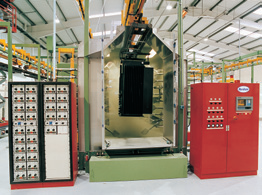
State-of-the-art painting line
A state-of-the-art painting line, incorporating zinc phosphating, electrically applied liquid paint and powder coating has been installed in the Irish factory. This system is one of the most up-to-date developments in the field of finishing and the quality obtained is comparable with that required by today’s automotive industry for modern car bodies. Tests by independent laboratories have shown
that transformer tanks treated in this way withstand more than 2,000 hours hot salt spray scribed test carried out in accordance with the relevant international standards.

Standard tanks are equipped with:
• securing lugs on the top frame of the tank to secure the transformer during transport
• lifting lugs on the cover to lift the complete transformer and/or the active part
• underbase welded to the bottom of the tank with bi-directional rollers (roller base)
• filling hole on the cover (can also be used to mount an overpressure valve)
• earthing terminals on tank cover and underbase or tank bottom
• thermometer pocket welded to the tank cover and filled with cooling liquid
• drain valve at the bottom of the tank (can also be used to take oil samples)
This standard package can be expanded to include other monitoring and protection instruments.
Finishing operations and testing
Mounting the active part in the tank
Once the active part has been oven-dried, it is given a final comprehensive quality inspection before being tanked. The top cover is then either bolted or welded onto the tank frame, in agreement with the customer. Both sealing methods are equally effective and performing. For silicone filled units we advise welded lids while for other liquids we have no preference.

Filling
The transformers are placed in a vacuum chamber and filled with pre-treated liquid (filtered, dried and degassed) under deep vacuum.
This ensures optimum impregnation of the insulation materials by the cooling liquid, giving the insulation structure maximum dielectric strength. Most transformers are filled with a high quality mineral oil which complies fully with the requirements of IEC standard 60296.
In some cases, transformers are filled with silicone liquid (complying with IEC 60836) or synthetic organic esters (complying with IEC 61099).
The liquid acts both as a coolant and as an insulating medium.

Testing
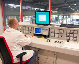
In the test bay, each transformer is subjected to a number of routine measurements and tests.

Fitting of protection equipment
Once routine testing is completed, the protection instruments and other acces-sories are mounted and the transformer is subjected to a final global inspection. Subsequently, the rating plate is fitted to the tank. The transformer is then ready for packing and transportation.
Routine measurements and tests
• Measurement of voltage ratios.
• Vector group test.
• Measurement of high voltage and low voltage winding resistances.
• Dielectric test of high voltage and low voltage winding(s) (1 minute at rated withstand voltage and nominal frequency). This test is also known as the “applied overvoltage test” and is intended to check the insulation of one winding from all other transformer components.
• Double voltage test (1 minute at double voltage and double frequency) induced via the low voltage winding. This is also known as the “induced overvoltage test” and is designed to check the insulation within each winding (turn to turn and layer to layer).
• Measurement of no-load losses and no-load current.
• Measurement of load losses and impedance voltage with the off-circuit tap changer in the nominal position.
• Measurement of the resistances of the insulating system between high voltage, low voltage and tank (Megger test).
Transformers and the environment
A growing importance is attached to the negative aspects of technology on people and the environment in modern society.
The potentially disturbing or hazardous aspects of transformers include:
• Noise pollution.
• Land pollution, due to escaping oil in case of leaks.
• The use of PCBs (polychlorinated biphenyls) in cooling liquids.
• Electromagnetic fields: the effects of such fields on humans, animals and instruments are not yet fully understood.
• Energy losses in transformers. This energy also has to be generated somewhere and this generation process has its own consequences, including a rise in emissions of harmful combustion gases.
• Visual pollution to the environment caused by the siting of transformers and substations without due consideration to the impact on the landscape.
• Safety of people and environment
Low-noise transformers
In many countries, there are strict limits on the noise levels which may be generated by transformers in both urban and rural locations.

The primary source of the noise produced is the alternating magnetization of the core steel, while the current carrying windings contribute only a very limited amount in distribution transformers.
CG Power Systems uses a variety of techniques to limit noise levels drastically, the most important being to reduce the induction in the core, producing an appropriate core shape (e.g. the step-lap method), a special clamping construction and the use of low-resonance tanks, etc. This enables CG Power Systems to build transformers with extremely low noise levels, down to within what we refer to as “whispering level”. The building of 630kVAs with noise levels below 30 dB(A) sound pressure at 1 m is an illustration of this. CG Power
Systems has also carried out pioneering work in the field of measurement of transformer-generated noise which lead to the official recognition of the noise intensity method in IEC 60076-10.
The sound intensity method allows more accurate measurement by eliminating disturbances due to the near-field effect and other nearby sources, and also enables the noise generated by the transformer to be measured when the ambient noise level is far in excess of the transformer noise. This clearly makes the noise measurement and evaluation process much simpler, while also allowing frequency analysis.
Reference table dB(A)
20 rustling of leaves
30 whispering
40 library
60 normal conversation
70 traffic noise
100 heavy machine shop
120 rock concert
130 pain threshold
Quality assurance certified to ISO 9001 and based on self-assessment
Protection equipment
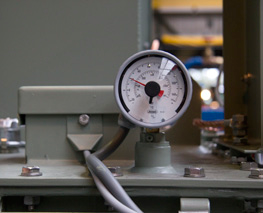
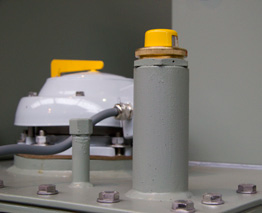
The most frequently fitted protection instruments
may be divided into seven groups:
1. Temperature monitoring
1.1. Monitoring the temperature of the cooling liquid
• Indicator thermometer with maximum pointer without electrical contacts
• Indicator thermometer with maximum pointer and two electrical contacts
• Remote thermometer with maximum pointer and two electrical contacts
• Thermostat with one or two electrical contacts
• PT 100 resistance-type thermometer

1.2. Monitoring the temperature of the windings
• Winding temperature indicator with maximum pointer and two electrical contacts
2. Liquid level monitoring
2.1. Liquid level monitoring in integrally filled and hermetically sealed transformers
• Vertical magnetic oil level gauge

2.2. Monitoring the liquid level in hermetically sealed transformers with gas cushion
• Float oil level indicator
• Oil level sensor with one electrical contact and optional gas sampling valve
2.3. Monitoring the liquid level in transformers fitted with a conservator
• Gauge glass
• Prismatic oil level gauge
• Horizontal magnetic oil level indicator without or with electrical contacts
3. Internal overpressure protection
• Pressure relief device without indicator
• Pressure relief device with indicator flag
• Overpressure relay with two electrical contacts

4. Protection of the liquid against moisture ingress
• Silica gel air dryer

5. Multi-purpose protection
• Buchholz relay with two normal (NO) contacts
• DGPT2 relay with four electrical contacts

6. Protection against physical contact
• Plug-in bushings and connectors (inside cone and outside cone model)
• Standard and special cable boxes

7. Overvoltage protection
• Arcing horns
• Surge arresters
For a more detailed description, ask our marketing communication department to send you the separate brochure on protection equipment.


